FREE-CARRIER ABSORPTION CALCULATOR
This calculator determines the fraction of infrared light absorbed by free carriers (electrons and holes) in a single pass through a semiconductor.
The calculator first determines the free-carrier absorption coefficient as a function of depth αFC(z). This depends on the choice of semiconductor, the net ionised dopant concentration Nnet(z), the temperature T, the wavelength of the incident light λ, and the free-carrier absorption model. Note that the choice of model has a significant impact on the output, and that PV Lighthouse is in the process of assessing the models for their relevance in assessing c-Si solar cells. Five such models are available; each is introduced below.
The calculator then discretises the doping profile, setting the nodes at equally spaced intervals, Δz, and computes the free-carrier absorption from one pass of light through the semiconductor by the sequence product,

where θ is the angle of transmission through the semiconductor, and imax is the node at which Nnet(zi) falls below 1e14 cm–3.
The calculations assume that (i) band-to-band absorption is negligible, and (ii) the free-carrier concentration equals the majority-carrier concentration in equilibrium, which equals the user-defined net ionised dopant concentration Nnet(z). The first approximation is valid when the incident photons have insufficient energy for band-to-band absorption, such as 1200 nm light in c-Si at room temperature. The second approximation is valid when the excess carrier concentration is negligible relative to the ionised doping concentration, such as in a heavily doped semiconductor or under low illumination.
THE AVAILABLE MODELS FOR FCA
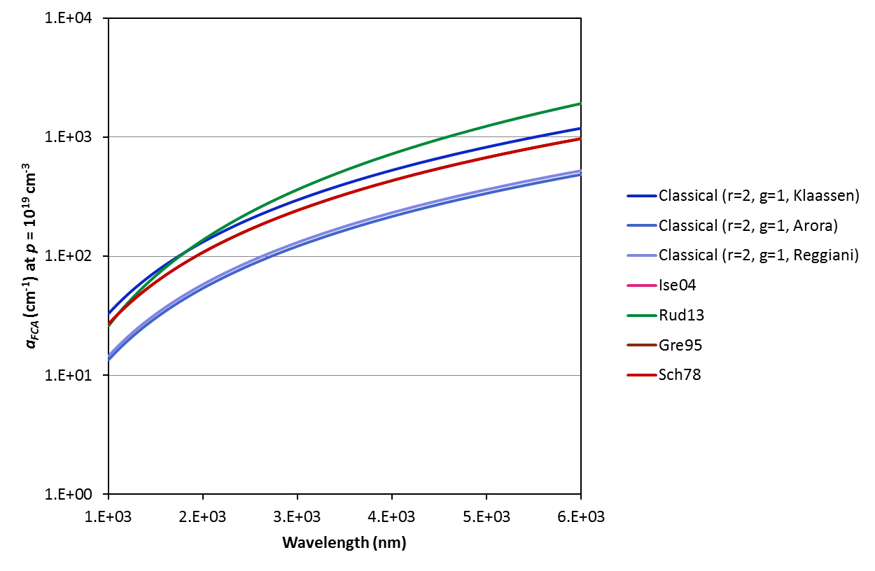
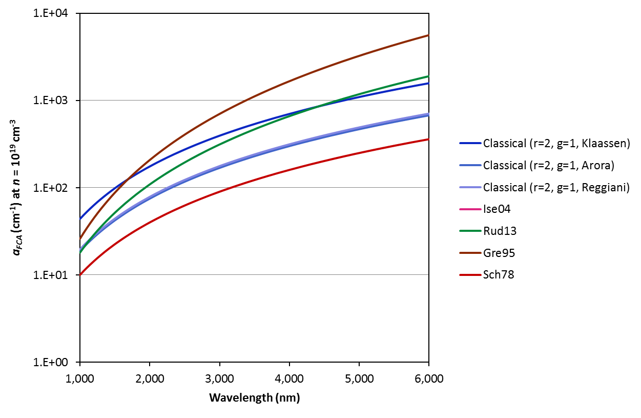
The first available model for the free carrier absorption coefficient is derived from the classical 'Drude' treatment of the random collisions of free carriers in a solid. Typically (eg. in [Sch78, Hor80, Ise04, Rud13]) the explanation of [Smi59] is cited. In the current embodiement of the model, we assume a linear dependence of the free carrier absorption coefficient on the carrier density and a parabolic dependence on the wavelength. We apply Equation 1 of [Sch78]. Input carrier densities are calculated per the Bandgap Calculator (ie. bandgap narrowing and incomplete ionisation can be taken into account), mobilities are calculated per the Mobility Calculator; both vary with temperature and dopant profile. In the current version, we assume the carrier conductivity mass to be constant with temperature and carrier concentration (we apply the values given at 300 K by [Rif02]). We are in the process of properly assessing these simplifications (with reference to [Sch67] and [Hor80] in particular).
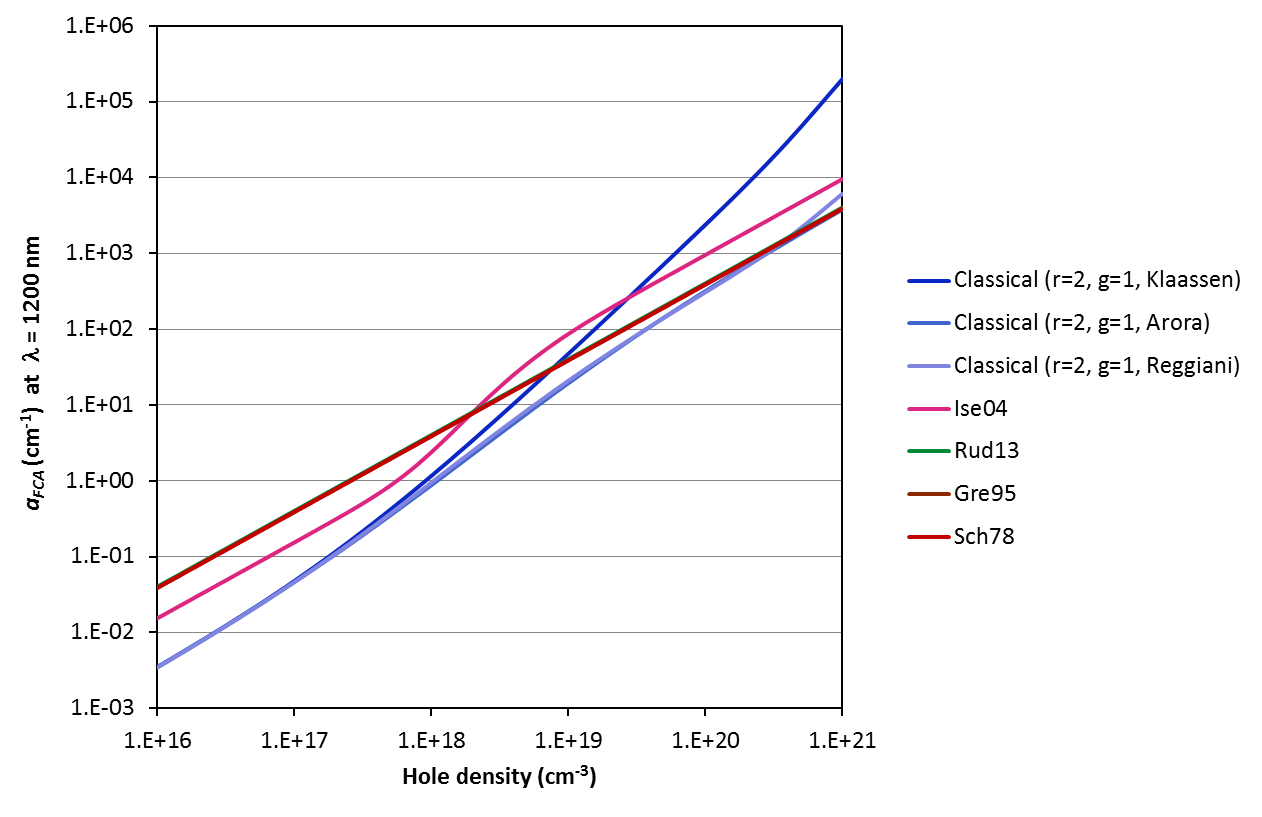
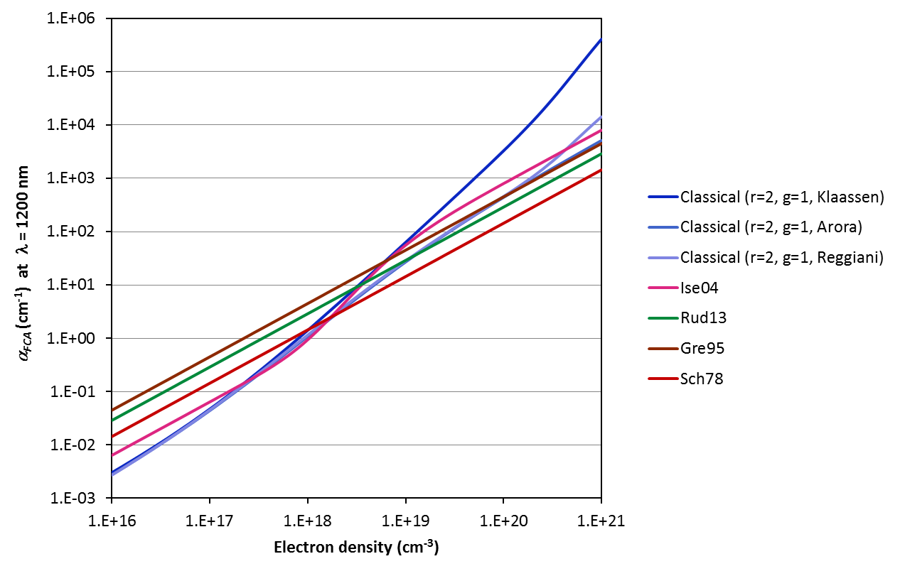
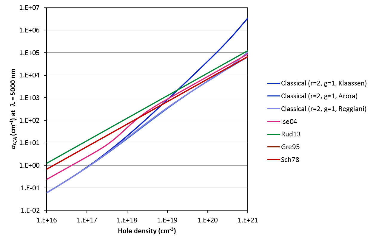
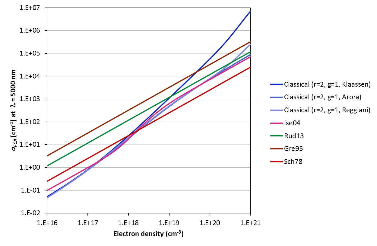
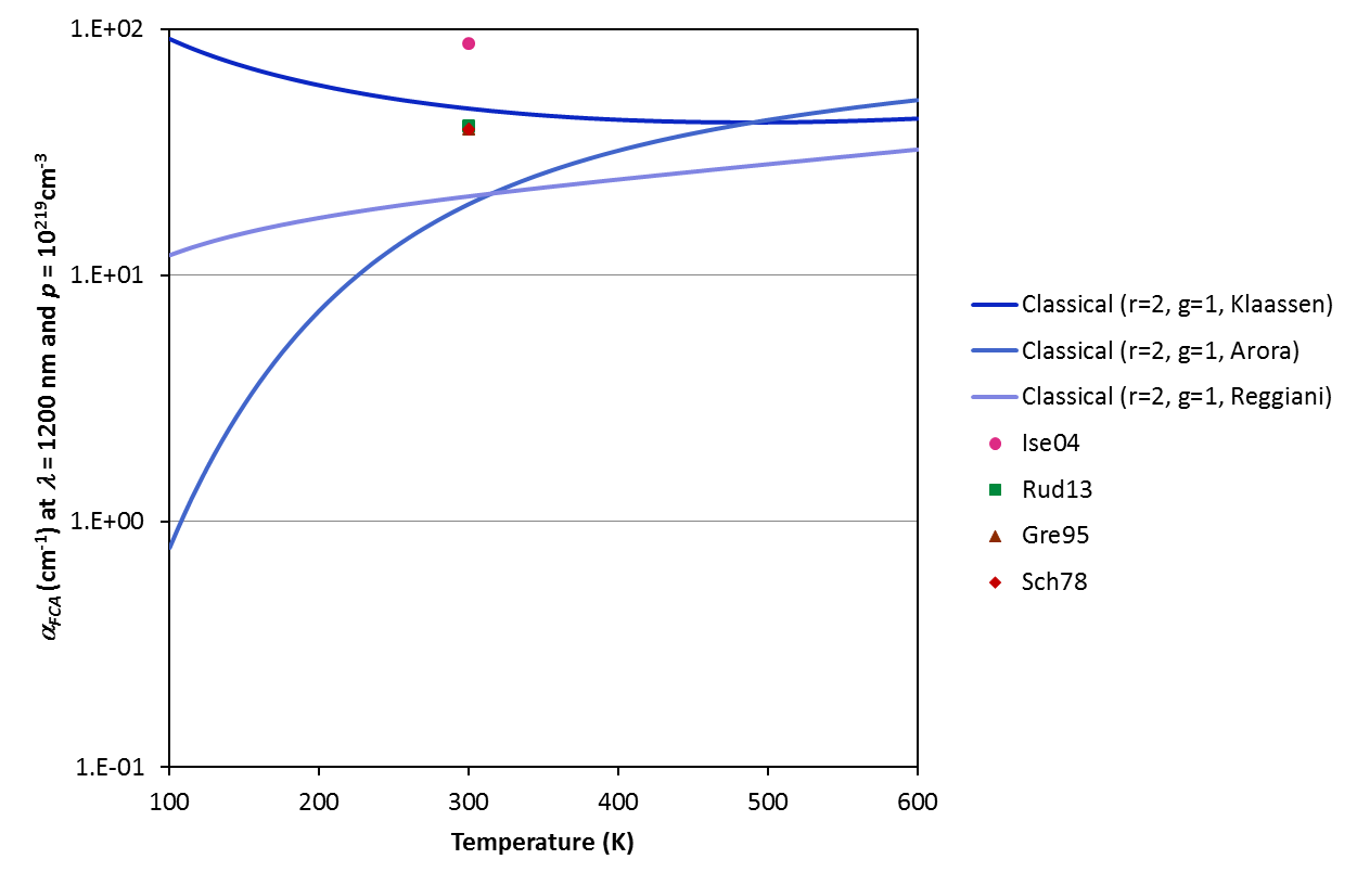
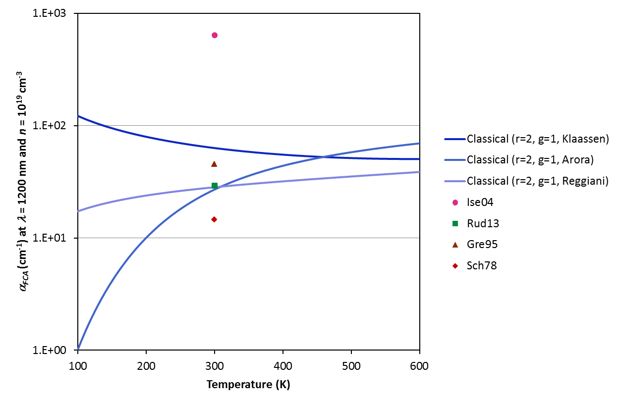
The four remaining models are parameterisations. (i) Schroder et al. [Sch78] (Equations 5 and 6) is based on a fit to data for wavelengths greater than 4000 nm and dopant concentrations ranging from 1016 to 1019 cm-3; (ii) Green [Gre95] (Equation 4.8) is said to be valid for wavelengths above approximately 2500 nm and carrier densities around 1018 cm-3; (iii) Isenberg and Warta [Ise04] (Equation 4 with parameters from Table I), which we limit it to the assessment of FCA at 300 K and 1200 nm; and, finally (iv) Rudiger et al. [Rud13], which is derived from a fit to data for FCA in diffused Si (carrier concentrations between 1017 and 1020 cm-3) at wavelengths between 1200 and 2000 nm.
COMPARISON OF MODELS
The various models and parameterisations available on this calculator predict strikingly different free carrier absorption coefficients. Refer to the examples below for the variation of the coefficient with excitation wavelength, carrier concentration and temperature. Note that the temperature dependence is a strong function of the mobility model chosen (for input to the Classical Drude equations); we urge caution when applying the model at temperatures other than 300 K. Refer to [Lee05] for experimental data that may or may not validate the Drude model in your investigated case.
EQUATIONS FOR THE DOPING PROFILE
Like PC1D, the user can select from four equations where all are defined by a peak concentration Np, the depth of the peak concentration zp, and a depth factor zf.
| Uniform: |
N(z) = Np for z ≤ zp and N(z) = 0 for z > zp |
| Exponential: |
N(z) = Np ⋅ exp[–|z – zp| / zf] |
| Gaussian: |
N(z) = Np ⋅ exp[–(z – zp)2 / zf2 ] |
| ERFC: |
N(z) = Np ⋅ {1 – erf[ (z – zp) / zf ] } |
Please note that in versions of this calculator earlier than 1.2.1 there was an error in the above equations as they were presented on this About page. The 'traditional' equations were displayed rather than those based on the PC1D approach. For a comparison of these two approaches please visit the Sheet Resistance Calculator. The front page of this calculator has always used the PC1D definition of the doping profile equations.
VERSION HISTORY AND BUG FIXES
| Version |
Release date |
Changes |
| 1.0.0 |
23-Jul-2012 |
Initial release of FCA calculator |
| 1.1.0 |
20-Aug-2013 |
Converted calculator over to new GUI design |
| 1.2.0 |
13-Sep-2013 |
Added four new models for free-carrier absorption. Updated the About page to include a description of the new models as well as a comparison between them. |
| 1.2.1 |
20-Aug-2013 |
Corrected the text in the about tab that described the doping equations. Previously the page displayed the equations based on the 'traditional' approach rather than the 'PC1D' approach used on the calculator main page. Thanks to the anonymous feedback that alerted us to the error. |
| 1.2.2 |
1-Oct-2013 |
Fixed a bug in the calculation of the impact of the bulk doping on the free carrier absorption. Previous versions only calculated the FCA in the bulk up to 1um of the end of the defined doped region, regardless of the bulk thickness entered. Additionally to this, if the bulk doping type was opposite the doping profile type then those background dopant atoms were subtracted from the total amount, reducing the effective doping concentration in the profile resulting in an error in the calculated FCA. Both of these errors have been corrected sorry for any inconvience caused. Any calculations made in which the bulk region was expected to be significant should be recalculated. A big thanks to Jerome Degallaix for finding this bug. |
| 1.2.3 |
18-Aug-2014 |
Added newly published FCA model of [Bak14]. |
REFERENCES
| | |
| [Bak14] | S.C. Baker-Finch, K.R. McIntosh, D. Yan, K.C. Fong and T.C. Kho, "Near-infrared free carrier absorption in heavily doped silicon," Journal of Applied Physics, 116, pp. 063106, 2014. |
| [Sch67] | PA. Schumann and RP. Phillips, "Comparison of classical approximations to free carrier absorption in semiconductors," Solid-State Electronics, 10, pp. 943–948, 1967. |
| [Sch78] | DK. Schroder, R. Noel Thomas and JC. Swarta, "Free carrier absorption in silicon," IEEE Journal of Solid-State Circuits, 13 (1), pp. 180–187, 1978. |
| [Hor80] | CM. Horwitz and RM. Swanson, "The optical (free-carrier) absorption of a hole-electron plasma in silicon," Solid-State Electronics, 23, pp. 1191–1194, 1980. |
| [Gre95] | MA. Green, "Silicon Solar Cells: Advanced Principles and Practice" p. 48, 1995. |
| [Ise04] | J. Isenberg and W. Warta, "Free carrier absorption in heavily doped silicon layers," Applied Physics Letters, 84 (13), pp. 2265–2267, 2004. |
| [Lee05] | BJ. Lee and ZM. Zhang, "Temperature and doping dependence of the radiative properties of silicon: Drude model revisited," Proceedings of the 13th International Conference on Advanced Thermal Processing of Semiconductors, pp. 251–260, 2005. |
| [Rif02] | DM. Riffe, "Temperature dependence of silicon carrier effective masses with application to femtosecond reflectivity measurements," Journal of the Optical Society of America, 19 (5), pp. 1092–1100, 2002. |
| [Rud13] | M. Rudiger, J. Greulich, A. Richter and M. Hermle, "Parameterisation of free carrier absorption in highly doped silicon for solar cells," IEEE Transactions on Electron Devices, 60 (7), pp. 2156–2163, 2013. |
| [Smi59] | RA. Smith, "Semiconductors" p. 219, 1959. |
FEEDBACK
Please email corrections, comments or suggestions to support@pvlighthouse.com.au.